
Insight 112 — Implant Impressions: Digital Scanning
In a digital impression, instead of a coping and impression material, we fasten a small component called a scan body onto the implant and the intraoral scanner records its surface. The scanner does not see the implant itself; only the shape of the scan body is recorded. The software calculates the position of the implant from this shape. So the accuracy of the work depends on two things: the scan body must be fully seated, and the software must identify it correctly.
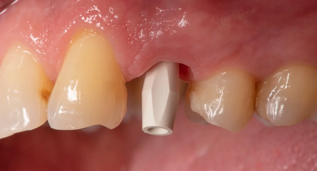
How the scan body transfers the implant position
A scan body is usually made of PEEK or titanium. Its lower part has the same connection as the implant, so, like a coping, it seats on the implant in only one orientation. Its upper part has a defined geometric shape, usually a flat or sloped surface, that indicates the rotational orientation and spatial position. After scanning, the 3D file of that same scan body is taken from the software’s library and matched onto the scanned shape. The software knows exactly where the implant sits relative to the scan body in the library file. So, through this matching, the location, depth, angulation and rotational orientation of the implant are reconstructed in the digital model. This time the analog and the model are virtual. If a physical model is needed, it is printed from this same file and a special analog for printed models (digital analog) is placed in it.
With this method the error of repositioning the coping and the distortion of the material no longer exist, but several new sources of error take their place.
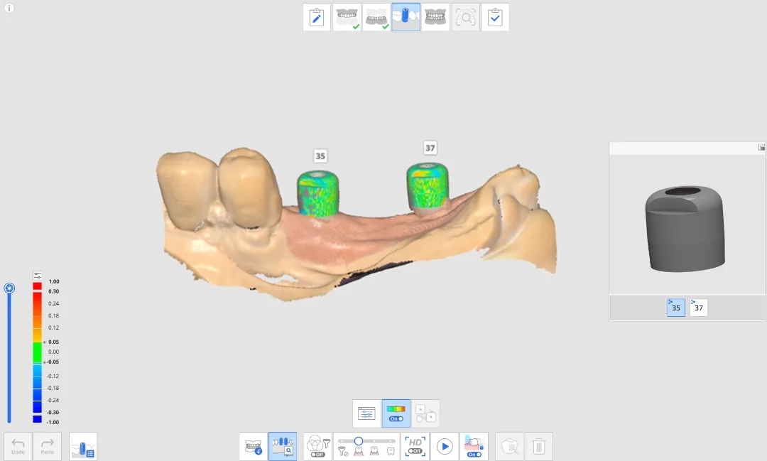
Where the scan body creates error
The first source of error is incomplete seating. The scan body must seat fully on the connection and its screw must be tightened by hand or to the torque specified by the manufacturer. If soft tissue or bone around the platform, for example in a deep implant, prevents complete seating, the software assigns that wrong position to the implant without any warning. Wherever we are in doubt, we check complete seating with a radiograph (details in the next part).
The second source of error is choosing the wrong library. Each scan body has its own library file. If the library does not match the brand and model of the scan body and the implant system, the match may look good but the implant may be reconstructed at the wrong height or position. That is why the type of scan body, the implant system and the platform diameter must be communicated precisely to the lab. It is better for the scan body and the Ti-Base, the titanium base onto which the crown is bonded, to be from the same brand.
The third source is wear and damage of the scan body itself. Many scan bodies are designed for a limited number of uses. A PEEK scan body wears with repeated sterilization and repeated tightening and removal, and its connection or identification surface changes. Scratches on the upper surface also spoil the match.
The fourth source of error is the quality of the scan itself. If part of the scan body surface is not recorded because of blood, saliva or gingiva, the software performs the match on an incomplete surface. The part of the scan body above the gingiva must be scanned completely and cleanly.
Recording the emergence profile
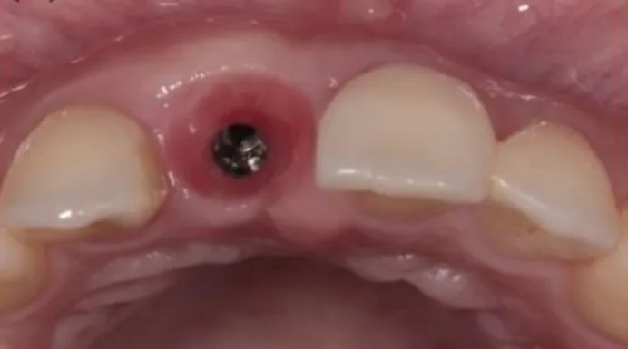
The scan body does not transfer the shape of the gingiva. On the other hand, when we remove the healing abutment or the provisional crown, the surrounding gingiva starts to collapse within a few minutes. There are two common approaches. The first is, immediately after removal, to scan the tissue itself without the scan body, then fasten the scan body and rescan only that area so that the software superimposes the two scans. The second, especially when the gingiva has been shaped with a provisional crown, is to scan the provisional crown itself. The provisional crown is scanned once in the mouth and once outside the mouth on an analog, with all its surfaces, so that its subgingival shape, which is the emergence profile, is transferred to the file.
Limitations in full arch and long spans
An intraoral scanner does not see the whole arch at once. It takes small images one after another and joins them together (stitching). With one or two implants next to natural teeth, the teeth are good reference points and the accuracy is clinically sufficient. In complete edentulism or a long span, there is only smooth, uniform gingiva between the scan bodies and few reference points for joining the images. The small error of each step accumulates, and the distance between implants on the two sides of the arch may shift enough for passive fit to be lost in a one-piece framework.
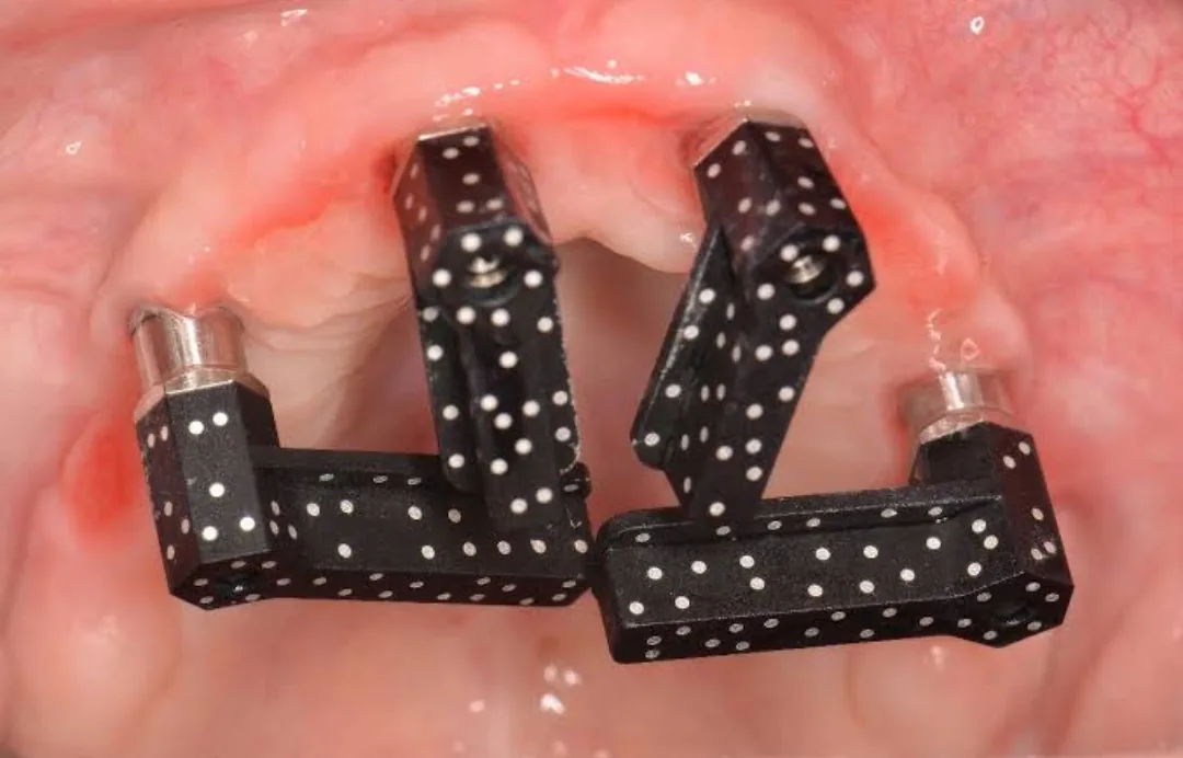
That is why in full-arch cases one of these two approaches is usually used alongside scanning. The first is photogrammetry. A special camera outside the mouth photographs special scan bodies with a coded pattern and measures their positions relative to each other directly, without joining images. In this case the positions of the implants come from photogrammetry and the shape of the tissue from the intraoral scan. The second is a verification jig: a rigid component made on the model, stone or printed, and tried in the mouth. If it seats on all the implants without stress, the model is correct.
The points that must be checked before sending the work to the lab, in both the conventional and the digital method, are the subject of the last part.
This page is intended for educational use by dentists and dental students.